
 |
 |
 |
 |
Except for deployment and recovery, the CTD
chain system is not labour intensive during operation. Watch keeping underway
can be put on any diligent person, if at least one specialist on measurements
in the ocean is at hand, who is familiar with the hard- and software of the
system. Duties of the watch-keeper are
The acquisition program
offers many display options. They can quite safely be changed by key commands
without influencing data acquisition. Dangerous key commands that would abandon
data storage require extra acknowledgement.
Two
ASCII files, which are required for data acquisition, should be prepared well
in advance of a deployment. The calibration file (a_name.CAL) contains
one line for each sensor fin. The sequence of lines is arbitrary. Each line
starts with the sensor address and a sensor type number followed by three times
three polynomial coefficients for the conversion of voltage readings of the
three measurement parameters into physical units. The configuration file (a_name.CFG)
has one line for each sensor fin in the sequence from the deepest to the
shallowest. The first column contains the sensor address, the second the
distance in tenths of metres from the tail of the chain, and the third a number
between 1 and 15 specifying one of 16 colours. The calibration and
configuration files are constituents of CTD chain data, since a binary chain
data file only holds voltage readings in the sequence specified by the
configuration. If it
is desired to test a CTD chain on shore, a few things must be preconceived.
Several hundred metres of insulated wire on a drum constitute a respectable
inductivity, against which the deck unit will likely not be able to operate.
There are two workarounds. The sensors may be stringed on a short laboratory
cable prior to configuration of the long chain. Or the long cable may be taken
from the drum and stretched out on the ground. A successful test does
however not guarantee flawless operation after deployment into the ocean. Due to energy loss into the surrounding water, a sensor fin in several hundred metres depth receives less energy from the deck unit and the amplitude of its answer is lower than that of a sensor fin positioned close to the
surface. Who wants to be sure that his deck unit
works with a several hundred metres long CTD chain, should once have tested the
system under real conditions at sea prior to a research cruise.
Sensor fins may optionally include a fourth parameter such as oxygen.
In order not to extend the sensor message by two more bytes, only three of
four parameters should be selected simultaneously, though. A CTD chain sensor configuration program
named CTDsc.exe is at the users disposal, by means of which the operation mode and operational parameters of
underwater units can be changed. CTDsc.exe replaces the older DOS program CTDSENS.EXE.
When the sensor configuration program is run, the same precautions must be taken as described below for the
acqusition program in order to avoid excessive supply current from the deck unit. Cruise
preparation includes the configuration of the wet part of the system. Although
the chain can well be reconfigured during the cruise, it is mostly preferred to
specify chain length and sensor fin separations for a complete cruise. Sensor
fins are fixed at their positions with stoppers, the spaces filled with
fairings, and the cable terminated with a thimble in advance. If the chain
shall be placed below a towed float, a water tight upper termination is
prepared, which includes an underwater connector for attachment to a single
conductor armed towing cable.
During
deployment the ship should be stopped or proceed extremely slowly ( < 2
knots). The depressor is deployed first. A swivel is inserted between the
depressor and the thimble at the lower end of the chain. Fairings are mounted
filling all space between sensor fins. The fairings are not only essential for
drag reduction, they also eliminate the risk of the cable insulation to be
damaged during deployment, especially if a chute is used instead of a pulley.
It is recommended to plug the upper end of the tow cable to the
slip ring of the winch, from where the connection with the deck unit via a single
conductor cable can be prepared well in advance. If the winch is not equipped with
a slip ring, the connection is established after the winch drum was rotated into
its final position. The deck unit or at least the power of the supply current source
of the CTD chain should remain off until data acquisition starts.
Technical details of operation in a DOS based system were described in the paragraph “Chain control and data acquisition” in the system
description. Prior to program launching under DOS, date and time should be accurately set
to the same time zone that is used in the (external) GPS navigation log,
preferably UTC. CTD chain records will
be triggered by the real-time clock of the acquisition PC. Date and time read
from the RTC are constituents of each data record. In a more modern configuration based on a Windows PC and USB link between PC and deck unit,
time stamps of the records are coming from an internal real-time clock inside the USB link.
The host computer initializes that real-time clock with system time (UTC) as soon as the “start deck unit”
button is clicked in the acquisition program. Subsequent time adjustments of the host computer, e.g.
by a time server, do not affect regular record timing of the CTD chain system. When the “start deck unit” command is isued, the USB link periodically switches the RTS signal
of the deck unit as described in Bus signals
and polls the sensors in the predefined sequence.
Not earlier than now the chain supply voltage should be switched on and
slowly increased to the level where
the sensor fins are sufficiently powered and their answers appear on the
graphic and
alphanumeric displays. The operator must bear in mind that after having
reached the appropriate supply voltage the overall impedance of the CTD
chain decreases with increasing supply voltage, i.e. the current can
suddenly increase. An excessive supply current of several Amperes may be
destructive. When the system runs correctly with all sensors working, writing into a
data file is started with an extra key command or button.
CTD chain data files always reside in the same directory with the
associated configuration and calibration files.
It is advised to store all data of a deployment phase into one single
contiguous file.
It is easier to postprocess and cut data files according to ship tracks
than to acquire short files that are postprocessed separately.
During acquisition, the graphical real-time display shows the most
recent data, one record per pixel column. The image is horizontally
scrolled as the measurements progress. Changing display parameters of the program does not interfere with data acquisition, which is interrupt
driven with higher priority. Additional tasks running on the acquisition PC do probably not disturb chain data acquisition,
except particularly demanding system tasks such as software updates. It is therefore advised not to allow the PC to be updated
during data acquisition. In case of missing service of the USB interface for more than 0.3 seconds, synchronization between
USB link and PC is lost and no more data acquired, although the link is still working and controlling the deck unit.
In that case the file should be closed, the USB connector unplugged for a few seconds, and the acquisition procedure
started from the beginning.
Often
it is preferred to store final data as calibrated and filtered physical values
and forget about raw data. This is e.g. agreeable for standard CTD casts which
are usually stored at fixed vertical intervals in contrast to raw time series.
For CTD chain data it is suggested to keep raw uncalibrated data and apply
calibration polynomials and seawater equations whenever chain data are
displayed or used for something else. Postprocessing
in this sense is restricted on the removal of occasional outliers which appear
due to byte transmission errors from the CTD chain to the deck unit, and on
fine tuning of polynomial coefficients. Fine tuning beyond nominal sensor
accuracy helps to remove bothering sensor trails in two-dimensional false
colour images of sea water properties. Experienced
Matlab users are invited to
use the functions of a CTD chain toolbox for data postprocessing and presentation.
|


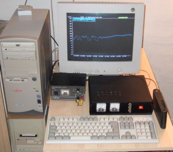 Running
CTDCHAIN.EXE for a single sensor fin in the laboratory.
Running
CTDCHAIN.EXE for a single sensor fin in the laboratory.
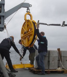 Crew
involved in chain deployment must be aware that sensor fins, though moulded
with robust and abrasion insensitive potting compound, are delicate
oceanographic instruments. Care must be taken that no fin interlocks at an
obstacle during deployment or recovery. Fins must be held in an upright
position when they pass the pulley or chute. The fin edge, which contains the
ferrite ring core of the inductive coupler, is protected by stoppers on both
sides, whose diameter is larger than the fin thickness. The usage of too small
pulleys on the chain’s path from the winch into the water would contradict the
protection by stoppers.
Crew
involved in chain deployment must be aware that sensor fins, though moulded
with robust and abrasion insensitive potting compound, are delicate
oceanographic instruments. Care must be taken that no fin interlocks at an
obstacle during deployment or recovery. Fins must be held in an upright
position when they pass the pulley or chute. The fin edge, which contains the
ferrite ring core of the inductive coupler, is protected by stoppers on both
sides, whose diameter is larger than the fin thickness. The usage of too small
pulleys on the chain’s path from the winch into the water would contradict the
protection by stoppers.