 |
 |
 |
 |
The
smallest CTD chain system consists of a deck unit and few sensor fins on a
short insulated steel rope with some ballast or depressor, light enough to be
deployed by hand over the railing. Larger systems require an efficient depressor with a swivel, an appropriate pulley
similar to the one shown on the overview page, cable fairings, and a winch. The
radius of the pulley and the winch drum must be sufficiently large that the
pressure during system deployment and recovery acts only on the stoppers on
both sides of a sensor fin, but not on the fin edge. The pulley may be replaced
by an adequately shaped chute. Since there is always a trade-off between
optimal area coverage and the breaking strength of the tow cable, fairings should
never be waived, unless the system is only used while drifting. Fairings reduce
cable tension and enlarge the depth range. The application of a cable tension
meter is highly recommended.
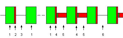
The
tow cable acts as a data bus. Each sensor fin has a unique 8-bit address. On
reception of its address a sensor fin transmits the contents of the output
buffers. The special address 0x00 is common to all sensor fins. It marks a
cycle start and compels the sensor firmware to transfer instant measurements
into the output buffers. This mechanism guarantees simultaneity within a chain
record irrespective of the polling sequence. Digital data are transferred
between deck unit and sensor fins as frequency encoded asynchronous serial
8-bit data plus parity. The bit rate is 9600 Baud. It takes about 9
milliseconds to send three 16-bit data items (T, C, P) and a checksum byte.
While listening for data the deck unit is silent and thus does not deliver
power to the fins. For
proper energy transfer the address sending time is extended to several
milliseconds. The sketch below
illustrates the timing of the CTD chain system.
The recurrent on-off of the supply signal is controlled by the acquisition program running on a DOS computer
or, newly, by a USB link between the deck unit and a PC running under
Windows.
The AC signal transmitted through the tow cable
and coupled to the sensor electronics is rectified and gathered in a capacitor
which feeds the internal voltage regulators. When the capacitor voltage rises
beyond an upper threshold, further supply is inhibited until the voltage drops
below a lower threshold. During supply rejection the input impedance of the
sensor fin becomes small. Therefore a
current leveller should limit the maximum current in the CTD chain cable.
Deck unit and data acquisition PC are separate items. An RS232 serial port interfaces deck unit. The RTS line of
this port is used to switch the deck unit between sending and listening.
Command bytes (addresses) are always issued at the end of a sending
period. The frequency of the transmission to the CTD chain changes between 51
and 41 kHz at serial
bit boundaries. When RTS drops off, the deck unit is ready to capture a
sensor response, which is frequency encoded at 68 and 77 kHz, after less than
0.5 milliseconds. Frequencies
are converted to binary signals and sent to the serial port.
The
concept for data acquisition and chain operation was developed in the nineties.
The acquisition program CTDCHAIN.EXE was written in Borland Pascal. It bends
interrupt vector towards own service routines. It reads from and writes
directly into ports of the PC hardware such as the UART, the 8253 timer, the 8259
interrupt controller, the CMOS Real time clock, the graphics controller and the
EGA graphics memory. Only a single task operation system lets a user program
take control over the most important hardware resources. A PC with an RS232
serial port (not an emulation via USB) running under DOS (not a DOS
emulation) is therefore required for CTD chain control and data acquisition, if first generation ctdchain software is used for operation.
Since DOS computers with EGA graphics and RS232 communications ports
have become outdated, it was time to change the data acquisition concept. Timing
and control was moved into a link, which merely consists of a micro-controller with
USB and serial communications ports. The link can be inserted between any deck
unit and the USB port of a computer. New deck units have the USB link on board already.
The first version of USB link firmware and the source code of a simple data acquisition program was
released to the community of CTD chain users in May 2009. The final version of AcqChain, a convenient data acquisition and visualsation application for Windows computers, was delivered in autums 2011.
For
further reading, e.g. about the measured temperature sensor response time or
about power supply conditions on long chains, you are referred to J.
Sellschopp, A towed CTD chain for
two dimensional high resolution hydrography,
Deep-Sea Research I, Vol. 44, No. 1, pp. 147-165 (1997). The CTD chain system
underwent modifications and enhancements since then, but the overall functional
description is still valid. |

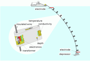 The
CTD chain consists of multiple fin-shaped CTD probes aligned on a coated steel
rope. In contrast to any other electronic oceanographic instrument, the
underwater units are neither plugged to a cable nor equipped with batteries and
data storage. Critical components such as underwater connectors, grommets and
flanges were avoided by inductive coupling of the underwater units to the tow
cable. The units may freely rotate on the cable, they are inhibited from gliding
by removable stoppers. The cable, which is led through a ring core located at
the edge of the sensor fin, acts as the primary coil of the inductive coupler
that powers the sensor electronics. AC voltage with frequency 51 kHz
is provided by a deck unit and fed into the tow cable. The primary circuit is
closed by the sea water connecting an electrode at the chain tail with an
electrode at the upper end or with the hull of the towing ship. Less than 1 Ampere
of primary current suffices to energize the sensor fins. The voltage depends on
the number of underwater units and the length of the chain.
The
CTD chain consists of multiple fin-shaped CTD probes aligned on a coated steel
rope. In contrast to any other electronic oceanographic instrument, the
underwater units are neither plugged to a cable nor equipped with batteries and
data storage. Critical components such as underwater connectors, grommets and
flanges were avoided by inductive coupling of the underwater units to the tow
cable. The units may freely rotate on the cable, they are inhibited from gliding
by removable stoppers. The cable, which is led through a ring core located at
the edge of the sensor fin, acts as the primary coil of the inductive coupler
that powers the sensor electronics. AC voltage with frequency 51 kHz
is provided by a deck unit and fed into the tow cable. The primary circuit is
closed by the sea water connecting an electrode at the chain tail with an
electrode at the upper end or with the hull of the towing ship. Less than 1 Ampere
of primary current suffices to energize the sensor fins. The voltage depends on
the number of underwater units and the length of the chain.
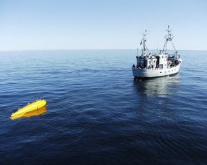 The
photograph on the left shows a considerable alternative to standard towing
directly from the deck. Here the CTD chain was deployed from the
German research vessel Planet together with a surface float. The tow cable and
the plug for the electronic deck unit was handed over to the cooperating
Swedish Urd, a boat of too small size for unassisted deployment, but
appropriate for towing. Aside from easy transfer, a CTD chain hanging below a
surface float has three more advantages. First, a float can be steered outside
the wake. Second, under high sea state conditions a float
moves less and thus produces less strain than the heaving stern. Finally, in
the unlikely case of an unpredicted underwater obstacle such as a drifting net,
the underwater system can be rescued if a weak link was included in the tow
cable in front of the float. As a drawback a system with float requires higher
effort during deployment and recovery.
The
photograph on the left shows a considerable alternative to standard towing
directly from the deck. Here the CTD chain was deployed from the
German research vessel Planet together with a surface float. The tow cable and
the plug for the electronic deck unit was handed over to the cooperating
Swedish Urd, a boat of too small size for unassisted deployment, but
appropriate for towing. Aside from easy transfer, a CTD chain hanging below a
surface float has three more advantages. First, a float can be steered outside
the wake. Second, under high sea state conditions a float
moves less and thus produces less strain than the heaving stern. Finally, in
the unlikely case of an unpredicted underwater obstacle such as a drifting net,
the underwater system can be rescued if a weak link was included in the tow
cable in front of the float. As a drawback a system with float requires higher
effort during deployment and recovery.